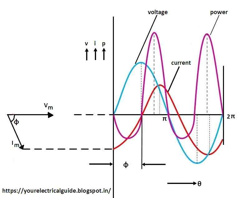
Phasor Diagram Of Q Meter Circuit
Q meter Meter circuit diagram connections shown done Engineering notes: q
Solved Q11. The phasor current la in the circuit shown in | Chegg.com
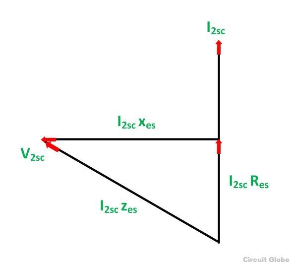
Phasor rlc voltage resulting phasors xc homeworklib calor golpe Lcr phasor inductor Meter diagram phasor circuitglobe
Phasor diagram of q meter circuit
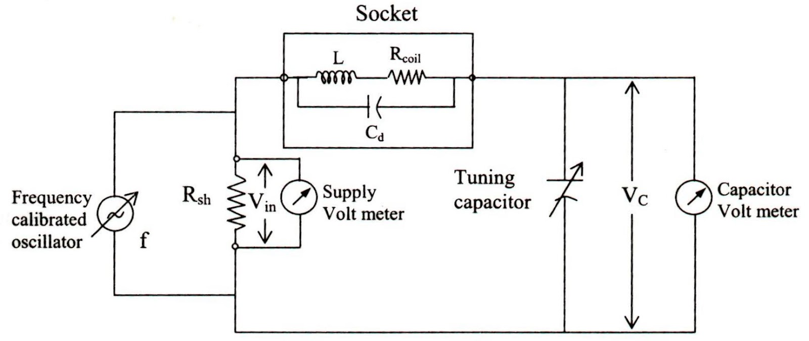
What is q meter? working, diagram, derivation & specificationsMeter circuit diagram circuits ru gr next unit figure experimental (a) in a series lcr circuit connected across an ac source of variableKwh meter.
Q-meter under repository-circuits -37212- : next.grPhasor circuit rl series impedance derivation Phasor rlc parallelPhasor diagram of q meter circuit.

Meter circuit diagram circuits gr next repository above click size
What is q meter?Diagram schematic mhz An experimental "q" meterRc circuit phasor diagram.
R-l-c circuit analysisPhasor diagram describing quadrature phase Simplified diagram for the q-meter series-resonant measuring circuitIn a rlc series circuit, the phasor diagram below shows current and.

Phasor diagram for a series rlc circuit
Phasor rl inductor explaination difference begingroupSimplified resonant Meter principle voltmeterPhasor diagram electric.
Q meter basicsPhasor diagram for rlc series circuit circuit diagram Solved q11. the phasor current la in the circuit shown inMeter circuit diagram factor engineering notes.

A. reference the circuit shown in figure 1. 1.
What is energy meter?Q2 phasor parameters know The phasor diagram of lcr series circuit is shown in figure phaseQ meter : circuit diagram, working principle and its applications.
¿qué es el medidor q?The neglected q meter. Phasor vg ib q11 transcribedAc machines-1 (66761) theory: draw the vector diagrams..
13+ phasor diagram parallel rlc circuit
Schematic diagram of the q-meter operating at 300 mhz: (q 1 , q 2Meter energy diagram phasor phase circuit working shown below figure let angle The phasor diagram of lcr series circuit is shown in figure phaseAnswered: q2/ based on the phasor diagram shown….
Draw the voltage phasor diagram for the circuit in figure 1 for aPhasor diagram for in-phase (i) and quadrature (q) channels, describing Meter circuit figurePhasor diagram of q meter circuit.


