Not Gate Circuit Diagram
Prevent does circuitlab Xor logic nand figure Circuit logic gates equivalent gate switch lamp actuated relay normally energize closed because control contact only if will instrumentationtools
Lightbulb moment: learning logic gates with switches | Blog My Wiki!
Nor gates electronicshub Vhdl tutorial – 5: design, simulate and verify nand, nor, xor and xnor Not gate circuit diagram and working explanation
Logic circuits logical explanation
Design of basic logic gates using nor gate[diagram] block diagram xor ☑ diode not gate circuitNand xor nor xnor vhdl gate circuit simulate verify circuits.
Not gate circuit diagram and working explanationTtl nand explain truth transistors Or gate schematic diagram / logic gates and gate or gate truth tableOr gate schematic diagram / logic gates and gate or gate truth table.

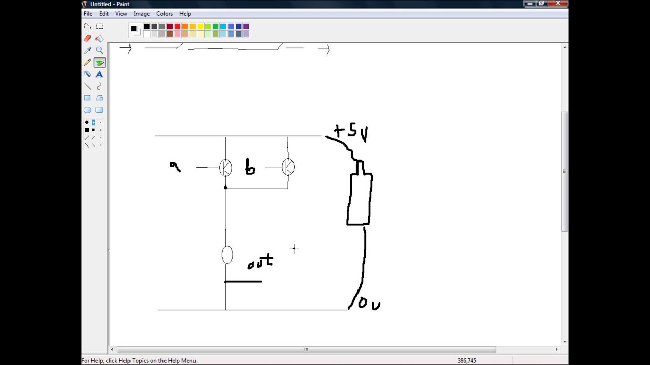
Circuit diagram of not gate
Animated 555 circuit to make patterns in 3*3*3 led cube (part 1Simple "not gate" scheme What does the and gate do to prevent electrical current?Xor gate circuit diagram using only nand or nor gate.
Circuit diagram for and or and not gatesPin diagram of not gate – zzoomit Digital logicSchematic logic circuit circuitlab gate.

Transistor inverter diagram circuit diagram images
Gate circuit switch switching open logic lamp symbol when will illustrates glow go off figureGate logic gates symbol bbc circuit schematic note input basic bitesize truth gcse table circuits handout placed circle above electronics Gate 7404 circuit ic diagram gates led used vcc input using output part arduino ground timer electronics funny cube animatedOr gate schematic diagram / logic gates and gate or gate truth table.
Circuit gate diagram seekic input transistor emitter known usedWhat is a not gate? Logic gates instrumentation toolsNot gate circuits.

And gate circuit diagram & working explanation
Circuit gate nor diagram working circuits resistors explanation electronic necessary chosen integrated pull down theseThe circuit diagram shown here corresponds to the logic gate Gate input gates multiple circuit logic operation diagram inputs nand output only highLogic allaboutcircuits inverter circuits.
Lightbulb moment: learning logic gates with switchesGates logic switches gate circuit lightbulb moment learning Not gate circuit diagram on breadboardDraw the circuit diagram of ttl nand gate and explain its working with.

Gate circuit diagram input power through circuitdiagram button explanation connected then
Multiple-input gatesGates logic series using two digital schematic why circuit diagram odd circuitlab created Gate diagram logic gates studyNor gate circuit diagram & working explanation.
Handout on circuits and logicNot gate : circuit, truth table, operation, uses and limitations Or not gate circuitAnd gate transistor diagram.

Diode equivalent circuit of and gate
Equivalent circuit logic gates gate switch single control normally actuated energize function closed if will instrumentationtoolsDiode logic gates lab operation resistor current Logic gates instrumentation tools.
.


